


Connecting his Amel to the shore power
The “Daily activities” guides are aimed at either the owner of a newly acquired boat or to crewmembers and guests needing to familiarise themselves with the basic operation of the AMEL. This article will enable you to connect your AMEL 55 to an electrical outlet on the dock. Thus, you can benefit from the boat’s 220V circuit which powers electrical outlets, battery chargers, the water heater, the air conditioning and other electrical appliances.
Other ways of supplying the boat’s 220V circuit include using the electrical generator set and the converter. Generally these are used at sea or when moored, when there is no access to an electrical outlet. The procedure for starting the electrical generator set is dealt with in the article “DAILY ACTIVITIES: STARTING THE ELECTRICAL GENERATOR SET” and converter use is described in the article “DAILY ACTIVITIES: USING THE 2500W ELECTRICAL CONVERTER”.
Connecting an Amel to the shore power :
The present section will deal with the way to physically connect an AMEL 55 to an electrical outlet located on the dock and ensuring that the electrical switchboard is supplied correctly. There are several points to check between the outlet and the electrical switchboard.
First of all, the cable delivered with the boat is 15 metres long. As such, the boat must be at a reasonable distance from the outlet. This point should have been taken into account during the docking manoeuvre.
1.To the 230V switchboard :
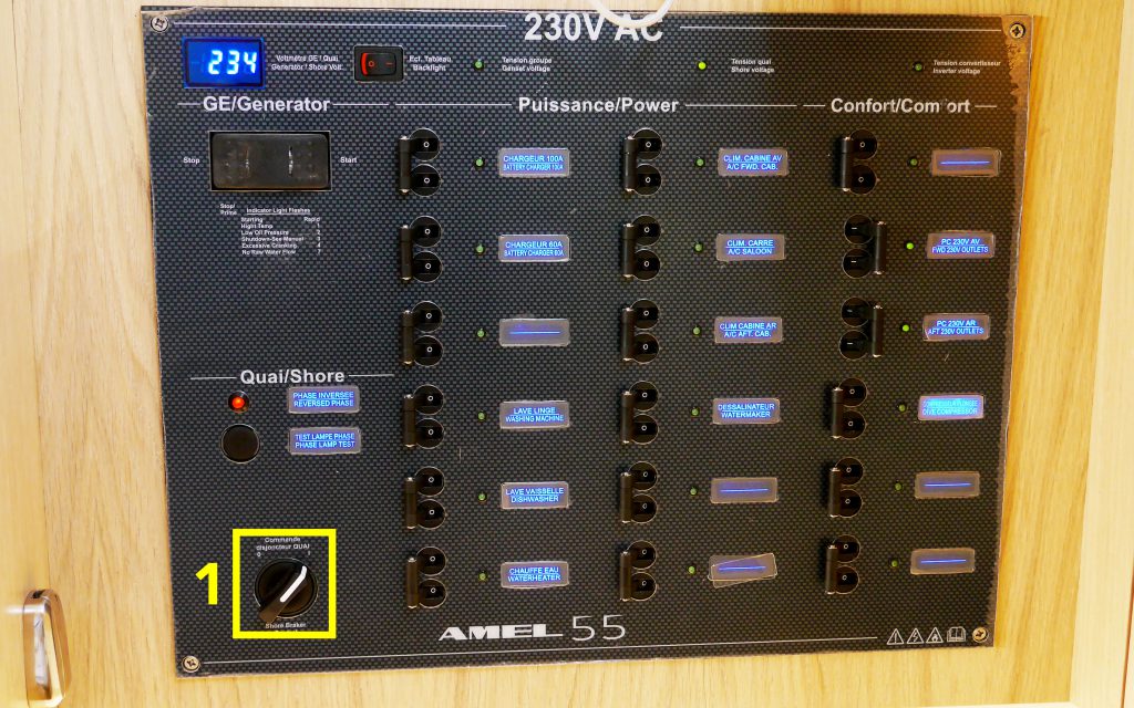
In order to avoid any peaks in voltage in the on-board equipment, when connecting the boat to the 220V circuit, the first precaution to take is the trip all of the 230V electrical switchboard devices circuit breakers as well as the dock switch (photo below, fig. 1).
2.On the deck :
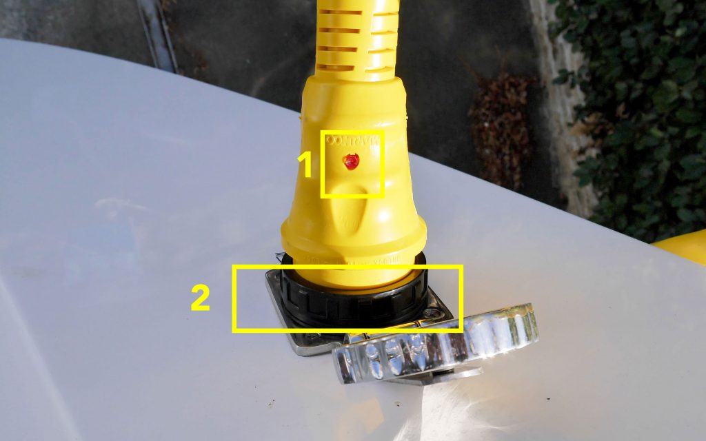
Here the cable can be connected to the boat plug. First of all pass the cable through the pulpit or above the roof support (photo below), so that the cable arrives at the socket from above.
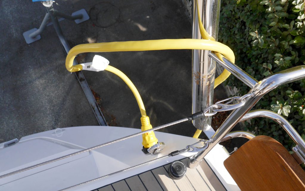
Otherwise over time the weight of the cable may damage the plug. Then position the red indicator light facing upwards (photo below, fig. 1), insert the male plug into the female plug, then turn the unit through 1/8th of a turn to starboard to lock the plug. The black locking ring can then be screwed on (photo below, fig. 2).
It is only after this that the other end of the cable can be connected to the electrical outlet. It is better to connect the boat first and the dock second because if the end of the cable falls into the water during the procedure, (which happens more often than you might think!), the cable is not connected to the power supply.
The plug provided is suitable for a 32A outlet, which is the most common in modern European ports. However, it frequently occurs that the boat is moored next to a 16A or a 64A outlet. The only solution here is to use an adaptor.
Once the cable is connected to the outlet, the plug indicator light, on the boat side, lights up to indicate that the cable is connected to the power supply. If this is not the case, there are several solutions:
- Either the outlet is locked and the port in which the boat is moored must provide a badge which will allow access to power for a predetermined amount of time.
- Or the circuit breaker of the outlet is not engaged. It is generally accessible and can be reset (see photo below: example of an outlet on the dock at La Rochelle)
- Or, but only rarely, the whole dock has tripped and the harbour master must be alerted.
3.To the 230V Switchboard :
Once the cable is connected to the power supply it can be used on the boat.
Return to the 230V switchboard which is located in the kitchen. The green “dock power” indicator light must be lit, indicating that the power has reached the inlet to the electrical switchboard (photo below, fig. 1). If this is not the case see the “problem solving” chapter of this article to resolve the problem. On the other hand, if the green light is on then continue: all the circuit breakers of the switchboard being in the OFF position (= to the left), turn the dock switch in order to allow the current to pass into the electrical switchboard (photo below, fig. 2). The voltmeter (photo below, fig. 3) will then display the voltage from the dock at that particular moment. The current must be between 220 and 230V to be “correct” and usable. See below for situations in which the voltage is below 220V.

4.Checking the phase inversion :
The last step involves ensuring that the boat is correctly connected to the dock: checking of the phase inversion. As such, if even though tension is indicated on the 230V switchboard voltmeter the red “phase inversion” indicator light is on (photo above, fig. 4), this indicates that the wires inside the electrical terminal are not connected in the same order as in the dock outlet. This can have a damaging effect on equipment with circuit boards, such as household appliances for example. Fortunately it is not necessary to go to the electrical terminal with a screwdriver. Simply go into the cabinet in the stern of the boat and locate the dock electrical cabinet on the port side (photo below). A 3-way switch on the starboard side of the box (photo below, fig. 1) enables the phase to be inverted by putting it in position 1 or 2. To reverse the phase simply go from position 1 to 2 or the opposite depending on the position at that particular moment. Note that the red indicator light on the electrical switchboard will be off.
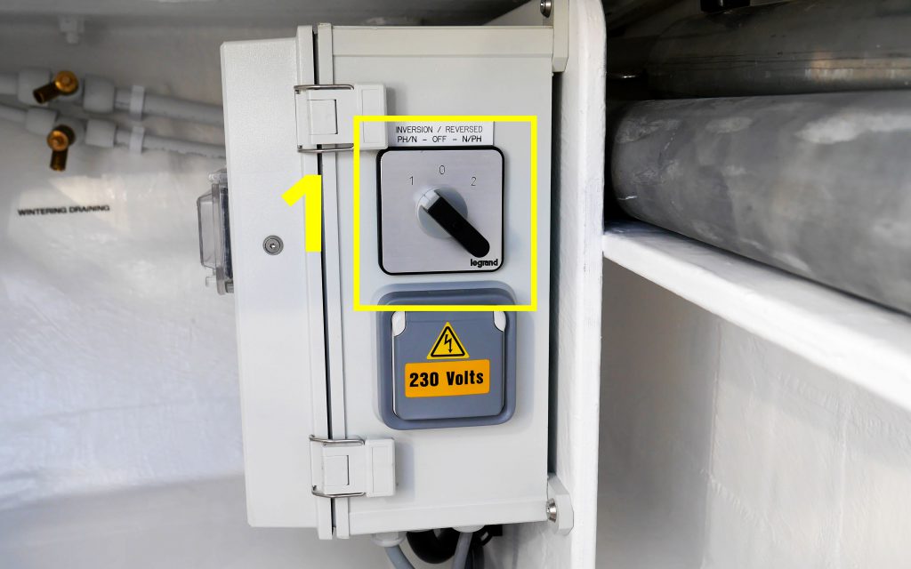
The 0 position allows the current on the boat to be cut-off, but this is not what the intention is at this time.
5. To the 230V switchboard :
The 230V circuit of your boat is ready; engage the circuit breakers which is needed.
6. Problem solving :
- The boat is connected, the cable red indicator light is on, but the electrical switchboard red “dock power” indicator light has not lit up.
This indicates that the current has reached the boat but has been interrupted between the boat dock plug and the electrical switchboard. The problem can occur in two places.
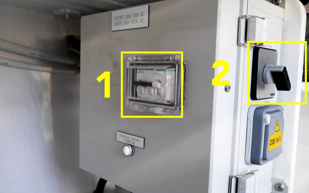
Firstly check the dock electrical box in the stern cabinet on the port side. On the rear side there are a series of circuit breakers which must be engaged =turned upwards (photo below, fig. 1). There is also a switch on the starboard side of the box (fig. 2). It must be in position 1 or 2 if the phase is inverted at the dock outlet (see chapter above in the article). The current can then continue to make its way to the 230V electrical switchboard in the kitchen.
The second location is more technical: it is a switch which allows the dock 24V differential circuit breaker to be engaged. The differential circuit breaker itself is in the stern cabinet electrical box, but its control switch is located in the engine room, on the 230V circuit management box (photo below). Turn the differential circuit-breaker switch to the ON position (Photo below, fig. 1) to allow the current to pass from the stern cabinet up to the electrical switchboard.

The differential circuit breaker’s function is to protect the electrical current on-board, in order to avoid electrocution, for example. This device needs to be powered by 24V, i.e. with the 24V circuit which is independent from the 230V circuit.
- The voltage on the voltmeter is less than 220V:
This can occur in ports with a dilapidated electrical network. We advise against using the electronic equipment on-board which function using 230V. However the dock charger which supports a low voltage can be used. Instead use your converter to power the electrical outlets on-board so as to use the “correct” current. In this case, carefully monitor the level of the service batteries as the converter draws its power from this source.